T1 Automatic Protection (Fail-Over) Switch
Orion Telecom Offers Power Utility Solutions Oil & Gas Networks Solutions Railway & Metro Rail Solutions PTP IEEE-1588v2 GPS Primary Reference Clock Packet Optical Transport Multiplexers Teleprotection SCADA, FOTE, OLTE Digital Cross Connects Echo Cancellers IP/Ethernet over TDM 1+1 APS (Fail-Over) Solutions Monitoring Groomer Solutions
Product Overview
Orion Telecom Networks Inc. offers 4 Port T1 Protection (Fail-Over) Switch allows the user to connect upto four T1 lines from the telephone company to "active", as well as to "standby" terminal(s), such as data server(s) etc. at the customer premises.
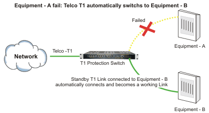
In the event of the failure of the data server(s) / equipment connected to the "A / active" ports, the T1 Protection (Fail-Over) Switch shall automatically switch and connect the T1 line(s) from the telephone company to the data server(s) / equipment connected to "B / standby" ports. This ensures minimum downtime -that would have otherwise occurred due to equipment failure. Enhances the efficiency of that network.

T1 Automatic Protection (Fail-Over) Switch - Data Sheet
Features and Highlights
- Allows the user to connect a T1 line from the Telephone Company and to switch it automatically between an "active" and a "standby" T1 terminal at the customer premises. The user programmable switching criterion may be Loss Of T1 Signal, AIS and Loss Of T1 Frame.
- Can accomodate upto four T1 lines - may be used switch between "active" and "standby" T1 terminals connected to upto four (or fewer) T1 lines.
- Independent switching for each of the four T1 lines.
- User programmable switching criterion - independent for each T1 line.
- Built-in real-time clock / real-time logging maintains a history of all events.
- Remotely accessible over a TCP-IP networks. Allows the user to access and carry out maintenance, or / and switch the T1 line(s) between the "active" and "standby" T1 terminals, remotely, if required.
- Allows the users to install and maintain active/standby/duplicate customer premises data networks/data servers, without bearing the recurring $$ expense of leasing additional expensive T1 lines from the telephone company.
- Automatically switches the T1 line from the Telephone Company between the "active" and "standby" T1 equipment at the customer premises, according to the customer-programmed criterion.
- Improves equipment and data security.
- Allows the user to co-locate the "backup / standby" equipment in a different room/building and prevent any data loss arising out of conditions of natural calamity such as fire, flooding etc.
- Increases the reliability of the customer's data/IT networks without having to bear the recurring and additional cost of leasing additional T1 lines from the telephone company. The equipment may be used to create secondary/backup systems at the customer premises to provide virtually uninterrupted service.
User programmable criterion for switching between Active and Standby T1 Links at the customers premises:
| Loss Of T1 Signal (LOS) |
The Loss of Signal condition in a T1 may occur due to:
The cause of LOF is 2 out of 5 Ft bits are in error for D4 Framing and 2 out of 5 frame bits are in error for ESF framing. |
| Loss Of Frame (LOF) | This Alarm is also known as Blue Alarm. This Alarm indicates unframed all ones being detected in the incoming pulses on the receiver of T1 Protection Switch. |
| Alarm Indication Signal (AIS) | This Alarm is also known as Yellow Alarm. This Alarm indicates in D4 Framed bit 2 of each DS0 for 255 consecutive channels has been detected as a zero. |
| Remote Alarm (RA) | When ESF Framed: Alternating eight ones/eight zeros have been detected in the ESF Datalink. A Yellow Alarm is typically transmitted to indicate a failure on the receive side of the Failed end. |
| CRC ERROR | This parameter is the number of CRC-6 errors (Cyclic Redundancy Check Errors) that occurred during the test period. CRC-6 errors are only counted while the Telco T1 framing is selected as ESF (Extended Superframe). The CRC-6 can be monitored either on In-Service or Out-of-Service T1 Spans. Since the expected value of the CRC pattern can be anticipated, the received data can be compared to the expected results. Whenever the expected value does not equal the actual value a CRC error event is counted. |
| Number of Interfaces | 4 Telco T1 Links (common link/Telco T1s) 4 Active T1 Links (for Equipment-A) 4 Standby T1 Links (for Equipment-B) |
| Line Rate | T1 - 1.544 Mbps |
| Line Code | B8ZS, AMI (User Selectable) |
| Frame Structure | SF, ESF (User Selectable) |
| Bit Rate | 1544 Kbps ± 50 ppm |
| Jitter Tolerance | As per ITU-T G.823 |
| Output Jitter | < 0.05 UI (in the frequency range of 20 Hz to 100 KHz) |
| Nominal Line Impedance | 100 Ohms Balanced RJ-45 |
| Nominal Pulse Width | 244 ns |
| Pulse Mask | As per ITU (CCITT) Rec. G.703 |
| Loss and recovery of frame alignment | As per clause 3 of ITU (CCITT) G.732 |
| Loss and recovery of multiframe alignment | As per clause 5.2 of ITU (CCITT) G.732 |
| Output voltage of AC Adapter | 100 - 240V AC |
| Range of input AC voltage | 100 V to 240 V AC, 50Hz / 60Hz. |
| System Input voltage | 7.5 V DC to 9.0 V DC with DC input polarity protection. |
| Maximum full load output current | 2.5 A at 7.5 V DC/9.0 V DC |
| Input voltage reversal protection | Provided in the Card |
| Efficiency at full load | >86% |
| Network Interface | RJ-45 Ethernet 10BaseT or 100BaseT-TX (auto sensing) |
| Compatibility | Ethernet Version 2.0 IEEE802.3 |
| Protocols Supported | ARP, UDP/IP, TCP/IP, Telnet, ICMP, SNMP, DHCP, BOOTP, TFTP, Auto IP, SMTP and HTTP |
| LEDs | 10Base-T and 100Base-TX Activity, full/half duplex |
| Management | Internal web server, SNMP (read only), Serial login, Telnet login |
| EMI Compliance |
|
| Rack mounting | Standard 19-Inch. DIN Rack |
| Height | 44.00 mm |
| Depth | 260.00 mm. |
| Width | 477.00 mm. |
| Weight | 4.00 kg. |
Command Language
- Command Line Interface (English text commands)
Management Ports (COM Port)
- Serial Port: 9.6Kbps (Async). ASCII/VT100/HyperTerminal
- 10BaseT Ethernet: Telnet
| Operating | 0°C to 50°C |
| Humidity | 5% to 95% Non-Condensing |
Application Diagrams
Application Diagrams
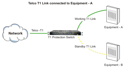
Applicaton # 1
Telco T1 Link Connected to Equipment - A

User programmable criterion for switching between Active and Standby T1 Links at the customers premises.
Applicaton # 2
Equipment - A Fails - Telco T1 automatically switches to Equipment - B

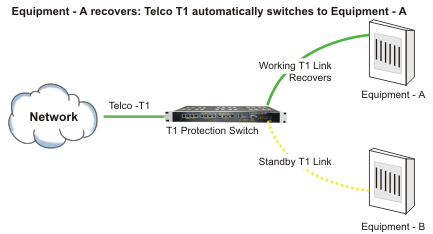
Applicaton # 3
Equipment - A recovers - Telco T1 automatically switches to Equipment - A

T1 Failover (T1 Automatic Protection) Switch - Data Sheet

